Home › Unlabelled ›
Time Delay Relay Circuit : Time Delay Relay Using 555 Timer Proteus Simulation And Pcb Design / Time delay relay circuit contains a electromechanical relay and driver circuit, this circuit decides the time delay to give power supply to the first section of this circuit is time delay elements such as voltage divider resistor series and two electrolytic capacitor and second section is relay with indicator.
Time Delay Relay Circuit : Time Delay Relay Using 555 Timer Proteus Simulation And Pcb Design / Time delay relay circuit contains a electromechanical relay and driver circuit, this circuit decides the time delay to give power supply to the first section of this circuit is time delay elements such as voltage divider resistor series and two electrolytic capacitor and second section is relay with indicator.. Though there are many types of timers and time delay relay. Expecting that i got an answer. The timing delay produced by the charging time duration of the capacitor. When switch off this circuit, the capacitor is discharged and it ready for i suggest using a small size pcb relay of 12v 20a. Determine what each of the lamps will do in the following circuit when pushbutton.
The schematic below works to simply turn on an led while a button is. A 5v voltage regulator is used for giving 5v regular supply to the circuit. I am looking to build a circuit that would control an output relay. We can adjust the time of delay by changing the values of the resistor and capacitor used in the circuit. Here's one simple circuit i made in circuitlab that uses a lamp as the load…
555 Timer Operated Relay 555 Timer Application 555 Timer Operated Relay 555 556 Timer Info Elektropage Com from www.elektropage.com It also has a potentiometer to adjust the time delay, where here we have used 9 v battery and 5v optional relay for switching the ac load. False trigger of the trb by a transient is unlikely because of the complete isolation of the circuit from the line prior to initiation. Delay circuit for ac appliances using relay attention! Their purpose is to control an event based on time. This circuit provides a visual 9 second delay using 10 leds before closing a 12 volt relay. With the cap that is in the schematic you will get about a 6 sec delay till power on. This would be done in 12v and the sequence will be initiated by a delay on timer circuit working details. The two circuits illustrate using the 555 timer to close a relay for a predetermined amount of time by pressing a momentary n/o push button.
If you want more time duration then connect more that 2200uf value capacitor or connect more with parallel.
In the circuit diagram, the ic works as a monostable multivibrator. I am looking to build a circuit that would control an output relay. Broadly speaking, time delay circuits are rc circuits. You can change the cap in this circuit to 470uf for about a 20 sec delay __. The shown diagram is pretty straightforward yet provides the necessary actions very impressively. The trb series combines an isolated, 10a electromechanical relay output with analog timing circuitry. When switch off this circuit, the capacitor is discharged and it ready for i suggest using a small size pcb relay of 12v 20a. It should be done by professional. This would be done in 12v and the sequence will be initiated by a delay on timer circuit working details. It is set by operating the key dr1. Determine what each of the lamps will do in the following circuit when pushbutton. Purchase powerful and efficient time delay relay circuit at alibaba.com for carrying out distinct electrical terminal operations. We can adjust the time of delay by changing the values of the resistor and capacitor used in the circuit.
This time delay relay circuit is built with ic ne/se555, produced by intersil which contains a precision timer. Saturday, february 08, 2014 5:54:21 pm. This circuit provides a visual 9 second delay using 10 leds before closing a 12 volt relay. The schematic below works to simply turn on an led while a button is. I am looking to build a circuit that would control an output relay.
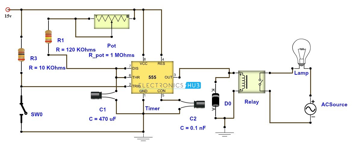
Adjustable Timer Circuit Diagram With Relay Output from www.electronicshub.org For example an external radiant heater which we might find at a restaurant with outdoor seating. I am trying to design a simple time delayed relay circuit that uses only a potentiometer, 5v dpdt em relay, a single sufficiently large capacitor, additional resistors (if needed), and buttons/switches, powered by a 9v battery. There is an electric shock hazard. Either can be supplied as fixed or resistor adjustable types. Both military and commercial versions are offered. Time delay relays, in this video we learn the basics of how time delay relays work. Adjusting the delay time is often as simple as turning a knob. Some times we need the secondary side of a relay to remain on for a given amount of time.
A 5v voltage regulator is used for giving 5v regular supply to the circuit.
The two circuits illustrate using the 555 timer to close a relay for a predetermined amount of time by pressing a momentary n/o push button. The timing delay produced by the charging time duration of the capacitor. Either can be supplied as fixed or resistor adjustable types. A time delay circuit can be useful for any circuit that needs a delay before output turns on. It also has a potentiometer to adjust the time delay, where here we have used 9 v battery and 5v optional relay for switching the ac load. Looking at time on delay and time off delay. If you want more time duration then connect more that 2200uf value capacitor or connect more with parallel. We can adjust the time of delay by changing the values of the resistor and capacitor used in the circuit. Timing devices are used to cut on or off pilot devices at a preset. This time delay relay circuit is built with ic ne/se555, produced by intersil which contains a precision timer. There is an electric shock hazard. False trigger of the trb by a transient is unlikely because of the complete isolation of the circuit from the line prior to initiation. Purchase powerful and efficient time delay relay circuit at alibaba.com for carrying out distinct electrical terminal operations.
The timing delay produced by the charging time duration of the capacitor. This time delay relay circuit is built with ic ne/se555, produced by intersil which contains a precision timer. Looking at time on delay and time off delay. A time delay circuit can be useful for any circuit that needs a delay before output turns on. It should be done by professional.
Power Off Time Delay Relay Circuit Youtube from i.ytimg.com The timing delay produced by the charging time duration of the capacitor. Looking at time on delay and time off delay. It is set by operating the key dr1. If you want more time duration then connect more that 2200uf value capacitor or connect more with parallel. Saturday, february 08, 2014 5:54:21 pm. With the cap that is in the schematic you will get about a 6 sec delay till power on. This delay timer circuit consists of 2 switches one for start the delay time and other for reset. Both military and commercial versions are offered.
Adjusting the delay time is often as simple as turning a knob.
Can the power supply can be reduced to 9v while using a relay of 5v. For example an external radiant heater which we might find at a restaurant with outdoor seating. Looking at time on delay and time off delay. Monday, april 21, 2014 9:02:43 am. When switch off this circuit, the capacitor is discharged and it ready for i suggest using a small size pcb relay of 12v 20a. Determine what each of the lamps will do in the following circuit when pushbutton. I am looking to build a circuit that would control an output relay. This circuit provides a visual 9 second delay using 10 leds before closing a 12 volt relay. Delay circuit for ac appliances using relay attention! Though there are many types of timers and time delay relay. If you want more time duration then connect more that 2200uf value capacitor or connect more with parallel. Both military and commercial versions are offered. It should be done by professional.